Showing posts with label CMOS. Show all posts

Apr 3, 2024

[paper] CMOS Technology for Analog Applications in High Energy Physics

Gianluca Traversi, Luigi Gaioni, Lodovico Ratti, Valerio Re and Elisa Riceputi
Characterization of a 28 nm CMOS Technology
for Analog Applications in High Energy Physics 
in IEEE Transactions on Nuclear Science
DOI: 10.1109/TNS.2024.3382348

1 INFN Pavia and Dipartimento di Ingegneria e Scienze Applicate, Uni. Bergamo, Italy
2 INFN Pavia and Dipartimento di Ingegneria Industriale e dell’Informazione, Uni. Pavia, Italy

Abstract: In the last few years, the 28 nm CMOS technology has raised interest in the High Energy Physics community for the design and implementation of readout integrated circuits for high granularity position sensitive detectors. This work is focused on the characterization of the 28 nm CMOS node with a particular focus on the analog performance. Small signal characteristics and the behavior of the white and 1/f noise components are studied as a function of the device polarity, dimensions, and bias conditions to provide guidelines for minimum noise design of front-end electronics. Comparison with data extracted from previous CMOS generations are also presented to assess the performance of the technology node under evaluation. 

Fig: Transconductance efficiency gm/ID as a function of the normalized
drain current IDL/W for NMOS (a) and PMOS (b) devices (|VDS| = 0.9 V)


Acknowledgment: The activity leading to the results presented in this paper was carried out in the framework of the Falaphel project, funded by the Italian Institute for Nuclear Physics (INFN). The authors wish to thank Prof. Massimo Manghisoni (University of Bergamo) for the valuable advice which contributed to improve this work and Dr. Stefano Bonaldo (University of Padova) for fruitful discussions on the measurement results. The authors wish to thank also Barbara Pini (INFN Torino) for the wire bonding of the chips, Emilio Meroni and Nicola Cattaneo (University of Bergamo) for the characterization activity.


Mar 18, 2024

[paper] Symmetric BSIM-SOI

Chetan Kumar Dabhi, Dinesh Rajasekharan, Girish Pahwa, Debashish Nandi, Naveen Karumuri, Sreenidhi Turuvekere, Anupam Dutta, Balaji Swaminathan, Srikanth Srihari, Yogesh S. Chauhan, Sayeef Salahuddin, and Chenming Hu
Symmetric BSIM-SOI: A Compact Model for Dynamically Depleted SOI MOSFETs 
 in IEEE TED (2024)
Part I DOI: 10.1109/TED.2024.3363110
Part II DOI: 10.1109/TED.2024.3363117

1 Department of Electrical Engineering and Computer Sciences, UCB, CA, USA
2 Department of Electrical Engineering, IIT Kanpur, India
3 GlobalFoundries, Bengaluru, India

Abstract: In this article, we present a symmetric surface-potential-based model for dynamic depletion (DD) device operation of silicon-on-insulator (SOI) FETs for RF and analog IC design applications. The model accurately captures the device behavior in partial depletion (PD) and full depletion (FD) modes, as well as in the transition from PD to FD, based on device geometry, doping, and bias conditions. The model also exhibits an excellent source–drain symmetry during dc and small-signal simulations, resulting in error-free higher order harmonics. The model is fully scalable with bias, temperature, and geometry and has been validated extensively with real device data from the industry. The symmetric BSIM-SOI model is developed in Verilog-A and compatible with all commercial SPICE simulators.

FIG: (a) Schematic of a typical SOI MOSFET
(b) Cgg versus Vgb for different substrate bias, with the PD-to-FD transition 

Acknowledgment: The authors thanks the members of the Compact Model Coalition (CMC), particularly Geoffrey J. Coram and Jushan Xie, for testing the model and suggesting improvements. The authors appreciate the CMC QA team’s efforts in conducting a model quality check. Caixia Han and Xiao Sun from Cadence provided a few useful test cases. They thank Ananth Sundaram and Anamika Singh Pratiyush from GlobalFoundries India for the help and discussion regarding DDSOI model intricacies and development. Model code is available at BSIM Website <https://bsim.berkeley.edu/models/bsimsoi/>


Jan 18, 2024

[paper] Open-source design of integrated circuits

Patrick Fath, Manuel Moser, Georg Zachl. Harald Pret
Open-source design of integrated circuits
Elektrotech. Inftech. (2024)
DOI: 10.1007/s00502-023-01195-5

* Institute for Integrated Circuits, Johannes Kepler University Linz, Austria

Abstract: This paper presents the design of a self-clocked 12-bit non-binary fully differential SAR-ADC using the SKY130 open-source PDK. The entire mixed-signal circuit design and layout were created with free and open-source software. The ADC reaches a sample rate of up to 1.44MS/s at 1.8V supply while consuming 703μW of power on a small 0.175mm area. A configurable decimation filter can increase the ADC resolution up to 16 bits while using an oversampling factor of 256. A 9‑bit thermometer-coded and 3‑bit binary-coded DAC matrix using a 448 aF waffle-capacitor results in a total capacitance of 1.83pF per input. Realizations of configurable analog functions using the form factor of SKY130 high-density standard cells allow the parametrization of an analog circuit in a hardware description language and hardening of the macro in an intentionally digital workflow.
FIG: Block diagram of the proposed open-source design flow,
including the essential tools and used/generated files

Acknowledgements: The authors thank Johannes Kepler University for funding the open-access publication, Google and SkyWater Technologies for igniting this recent wave of open-source IC design, and the large crowd of enthusiasts spending their time on developing and maintaining an extensive array of exciting open-source EDA projects. Open access funding provided by Johannes Kepler University, Linz.

Nov 1, 2023

[paper] Cryogenic Devices for Quantum Technologies

Jorge Pérez-Bailón, Miguel Tarancón, Santiago Celma, and Carlos Sánchez-Azqueta
Cryogenic Measurement of CMOS Devices for Quantum Technologies
IEEE Transactions on Instrumentation and Measurement (2023)

Quantum Materials and Devices (Q-MAD) Group
Institute of Nanoscience and Materials of Aragón (INMA),
Group of Electronic Design (GDE), University of Zaragoza (SP)

Abstract: In this article we present the experimental characterization of active components of a standard 65nm CMOS technology for a temperature range from 313 to 5K, analyzing the variation of the main parameters over temperature and voltage, recovering their main parameters (threshold voltage Vth, transconductance Gm and channel conductance GDS). The measurement has been carried out wire-bonding the bare dies with the devices to a dedicated printed circuit board (PCB) that has been placed inside a dilution refrigerator. The ID-VDS curves for both NMOS and PMOS transistors shows an increase of ID in the cryogenic regime that is more relevant for high values of VGS because for lower values it is partially compensated by the variation of Vth. Also, a kink is observed in these curves for high VDS values, caused by the bulk current generated by impact ionization at the drain combined with the increased resistivity of the frozen-out substrate. The transconductance Gm reaches non-zero values for higher VGS as T decreases, and then peaks to higher values in the cryogenic regime. In turn, GDS increases for increasing T, following the behavior observed for ID. Both results are in accordance with other thermal characterizations carried out on CMOS transistors in different technologies.

Fig: Detail of the IC in the measurement setup to fit into the cryostat

Aknowlegemetns: This work was supported in part by the Spanish Ministry of Science and Innovation under Grant PID2020-114110RA-I00; and in part by the CSIC Program for the Spanish Recovery, Transformation and Resilience Plan funded by the Recovery and Resilience Facility of the European Union, established by the Regulation (EU) 2020/2094 under Grant 20219PT007


Jun 27, 2023

[paper] Logic Without CMOS

Jonathan Hall and Manus Hayne
Logic Without CMOS: A III-V Semiconductor, Single Charge Carrier Approach to Digital Logic
WOCSDICE-EXMATEC 2023, Palermo (Italy), 21-25 May 2023

Department of Physics, Lancaster University, Lancaster, United Kingdom

Abstract: A new patent-pending approach to digital logic devices is proposed as an alternative to complimentary metal-oxide-semiconductor (CMOS) logic. A novel III-V semiconductor digital logic device combines both the “n” and “p” equivalents of CMOS into a single heterostructure device using just one type of charge carrier. The device, which forms an inverter, consists of two charge-accepting channel layers which sandwich a central electron (or hole) reservoir. Under zero bias the charge remains in the reservoir with both channel layers absent of free charge carriers (off state). Once a bias is applied to the gate, charge is either pushed into the bottom channel (negative bias) or pulled into the top channel (positive bias) turning one channel on whilst the other remains off. Thus, the complementary behaviour of logic, in which one part of the logic element is on and the other is off, is achieved without the asymmetry of hole and electron mobility. Proof of concept devices have been designed in both the well documented GaAs/AlxGa1-xAs system and in the 6.1Å family of semiconductors. One-dimensional, room temperature energy-band simulations using nextnano++ (software for semiconductor devices) [1] have shown effective and symmetric logic function at low voltage and an excess of 1,000× charge density ratio between the two channels under operation. Proof of concept devices are currently undergoing fabrication.

Fig: Proposed device architecture for an inverter, utilising electrons as the charge carrier. The “N” and “P” charge-accepting layers represent the equivalent CMOS transistors. With positive VG, the electrons are pulled from the reservoir into the upper channel, and with negative VG, the electrons are pushed into the lower channel. With zero bias, the charge remains within the reservoir and the channels are resistive (off). The barrier layers can consist of grown semiconductor or deposited dielectric.

Acknowledgments: Thanks to the Leverhulme Trust for a PhD studentship for Jonathan Hall and to nextnano for access to their software.


Jun 13, 2023

[paper] Microchips for Memristive Applications

Kaichen Zhu, Sebastian Pazos, Fernando Aguirre, Yaqing Shen, Yue Yuan, Wenwen Zheng, Osamah Alharbi, Marco A. Villena, Bin Fang, Xinyi Li, Alessandro Milozzi, Matteo Farronato, Miguel Muñoz-Rojo, Tao Wang, Ren Li, Hossein Fariborzi, Juan B. Roldan, Guenther Benstetter, Xixiang Zhang, Husam N. Alshareef, Tibor Grasser, Huaqiang Wu, Daniele Ielmini & Mario Lanza 
Hybrid 2D–CMOS microchips for memristive applications
Nature 618, 57–62 (2023)
DOI: 10.1038/s41586-023-05973-1

Abstract: Exploiting the excellent electronic properties of two-dimensional (2D) materials to fabricate advanced electronic circuits is a major goal for the semiconductor industry1,2. However, most studies in this field have been limited to the fabrication and characterization of isolated large (more than 1 µm2) devices on unfunctional SiO2–Si substrates. Some studies have integrated monolayer graphene on silicon microchips as a large-area (more than 500 µm2) interconnection3 and as a channel of large transistors (roughly 16.5 µm2) (refs. 4,5), but in all cases the integration density was low, no computation was demonstrated and manipulating monolayer 2D materials was challenging because native pinholes and cracks during transfer increase variability and reduce yield. Here, we present the fabrication of high-integration-density 2D–CMOS hybrid microchips for memristive applications—CMOS stands for complementary metal–oxide–semiconductor. We transfer a sheet of multilayer hexagonal boron nitride onto the back-end-of-line interconnections of silicon microchips containing CMOS transistors of the 180 nm node, and finalize the circuits by patterning the top electrodes and interconnections. The CMOS transistors provide outstanding control over the currents across the hexagonal boron nitride memristors, which allows us to achieve endurances of roughly 5 million cycles in memristors as small as 0.053 µm2. We demonstrate in-memory computation by constructing logic gates, and measure spike-timing dependent plasticity signals that are suitable for the implementation of spiking neural networks. The high performance and the relatively-high technology readiness level achieved represent a notable advance towards the integration of 2D materials in microelectronic products and memristive applications.

FIG: Structure of the considered SNN. Each MNIST image is reshaped as a 784x1 column vector, and the intensity of the pixels is encoded in terms of the firing frequency of the input neurons. The only trainable synapses are those connecting the input layer with the excitatory layer, and they are modelled with the STDP characteristic of the CMOS-h-BN based 1T1M cells. The learning is unsupervised, and the neurons are labelled only after the training. These label-neuron assignments are then feed to the decision block altogether with the firing patterns of the neurons, to infer the class of the image presented in the input. 

Acknowledgements: This work has been supported by the Ministry of Science and Technology of China (grant nos. 2019YFE0124200 and 2018YFE0100800), the National Natural Science Foundation of China (grant no. 61874075) and the Baseline funding scheme of the King Abdullah University of Science and Technology.

May 30, 2023

[PhD Thesis] Digital-based analog processing in nanoscale CMOS ICs for IoT applications

Digital-based analog processing in nanoscale CMOS ICs for IoT applications
http://hdl.handle.net/10183/249786
PhD Cadndiate: Pedro Filipe Leite Correia De Toledo
Universidade Federal do Rio Grande do Sul. Instituto de Informática
Programa de Pós-Graduação em Microeletrônica.
Advisor: Klimach, Hamilton Duarte
Co-advisor: Crovetti, Paolo Stefano

Abstract: The Internet-of-Things (IoT) concept has been opening up a variety of applications, such as urban and environmental monitoring, smart health, surveillance, and home automation. Most of these IoT applications require more and more power/area efficient Complemen ary Metal–Oxide–Semiconductor (CMOS) systems and faster prototypes (lower time-to market), demanding special modifications in the current IoT design system bottleneck: the analog/RF interfaces. Specially after the 2000s, it is evident that there have been significant improvements in CMOS digital circuits when compared to analog building blocks. Digital circuits have been taking advantage of CMOS technology scaling in terms of speed, power consumption, and cost, while the techniques running behind the analog signal processing are still lagging. To decrease this historical gap, there has been an increasing trend in finding alternative IC design strategies to implement typical analog functions exploiting Digital in-Concept Design Methodologies (DCDM). This idea of re-thinking analog functions in digital terms has shown that Analog ICs blocks can also avail of the feature-size shrinking and energy efficiency of new technologies. This thesis deals with the development of DCDM, demonstrating its compatibility for Ultra-Low-Voltage (ULV) and Power (ULP) IoT applications. This work proves this statement through the proposing of new digital-based analog blocks, such as an Operational Transconductance Amplifiers (OTAs) and an ac-coupled Bio-signal Amplifier (BioAmp). As an initial contribution, for the first time, a silicon demonstration of an embryonic Digital-Based OTA (DB-OTA) published in 2013 is exhibited. The fabricated DB-OTA test chip occupies a compact area of 1,426 µm2 , operating at supply voltages (VDD) down to 300 mV, consuming only 590 pW while driving a capacitive load of 80pF. With a Total Harmonic Distortion (THD) lower than 5% for a 100mV input signal swing, its measured small-signal figure of merit (FOMS) and large-signal figure of merit (FOML) are 2,101 V −1 and 1,070, respectively. To the best of this thesis author’s knowledge, this measured power is the lowest reported to date in OTA literature, and its figures of merit are the best in sub-500mV OTAs reported to date. As the second step, mainly due to the robustness limitation of previous DB-OTA, a novel calibration-free digital-based topology is proposed, named here as Digital OTA (DIG OTA). A 180-nm DIGOTA test chip is also developed exhibiting an area below the 1000 µm2 wall, 2.4nW power under 150pF load, and a minimum VDD of 0.25 V. The proposed DIGOTA is more digital-like compared with DB-OTA since no pseudo-resistor is needed. As the last contribution, the previously proposed DIGOTA is then used as a building block to demonstrate the operation principle of power-efficient ULV and ultra-low area (ULA) fully-differential, digital-based Operational Transconductance Amplifier (OTA), suitable for microscale biosensing applications (BioDIGOTA) such as extreme low area Body Dust. Measured results in 180nm CMOS confirm that the proposed BioDIGOTA can work with a supply voltage down to 400 mV, consuming only 95 nW. The BioDIGOTA layout occupies only 0.022 mm2 of total silicon area, lowering the area by 3.22X times compared to the current state of the art while keeping reasonable system performance, such as 7.6 Noise Efficiency Factor (NEF) with 1.25 µVRMS input-referred noise over a 10 Hz bandwidth, 1.8% of THD, 62 dB of the common-mode rejection ratio (CMRR) and 55 dB of power supply rejection ratio (PSRR). After reviewing the current DCDM trend and all proposed silicon demonstrations, the thesis concludes that, despite the current analog design strategies involved during the analog block development

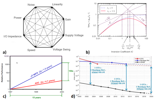
Fig: a) analog design octagon; b) gm/ID·fT versus the inversion coefficient IC, λc is the parameter corresponding to the fraction of the channel in which the carrier drift velocity reaches the saturated velocity over a portion of the channel geometrical length; c) Performance difference between analog and digital blocks over time; d) Area reduction over the years of the bitcell SRAM, OTA and bandgap reference

May 26, 2023

[paper] integrated PD SOI CMOS microcantilever biosensor

Yi Liu, Yuan Tian, Cong Lin, Jiahao Miao & Xiaomei Yu*
A monolithically integrated microcantilever biosensor 
based on partially depleted SOI CMOS technology
Microsystems & Nanoengineering volume 9, Article number: 60 (2023)
DOI: 10.1038/s41378-023-00534-y

* School of Integrated Circuits, Peking University, National Key Laboratory of Science and Technology on Micro/Nano Fabrication, Beijing, 100871, China

Abstract: This paper presents a monolithically integrated aptasensor composed of a piezoresistive microcantilever array and an on-chip signal processing circuit. Twelve microcantilevers, each of them embedded with a piezoresistor, form three sensors in a Wheatstone bridge configuration. The on-chip signal processing circuit consists of a multiplexer, a chopper instrumentation amplifier, a low-pass filter, a sigma-delta analog-to-digital converter, and a serial peripheral interface. Both the microcantilever array and the on-chip signal processing circuit were fabricated on the single-crystalline silicon device layer of a silicon-on-insulator (SOI) wafer with partially depleted (PD) CMOS technology followed by three micromachining processes. The integrated microcantilever sensor makes full use of the high gauge factor of single-crystalline silicon to achieve low parasitic, latch-up, and leakage current in the PD-SOI CMOS. A measured deflection sensitivity of 0.98 × 10⁻⁶ nm−1 and an output voltage fluctuation of less than 1 μV were obtained for the integrated microcantilever. A maximum gain of 134.97 and an input offset current of only 0.623 nA were acquired for the on-chip signal processing circuit. By functionalizing the measurement microcantilevers with a biotin-avidin system method, human IgG, abrin, and staphylococcus enterotoxin B (SEB) were detected at a limit of detection (LOD) of 48 pg/mL. Moreover, multichannel detection of the three integrated microcantilever aptasensors was also verified by detecting SEB. All these experimental results indicate that the design and process of monolithically integrated microcantilevers can meet the requirements of high-sensitivity detection of biomolecules.

FIG: a) Micrograph of the fabricated integrated microcantilever sensor IC.
b) SEM photograph of the microcantilever array

Acknowledgements: This research was funded by the National Natural Science Foundation of China (Grant No. 61935001).

Open Access: this article is licensed under a Creative Commons Attribution 4.0 International License 

May 17, 2023

[chapter] Systematic Design of Analog CMOS Circuits with Lookup Tables

Systematic Design of Analog CMOS Circuits with Lookup Tables
By Paul G. A. Jespers, Université Catholique de Louvain, Belgium

in Foundations and Trends in Integrated Circuits and Systems
Vol. 2: No. 3, pp 193-243. http://dx.doi.org/10.1561/3500000004

Publication Date: 08 May 2023
© 2023 P. G. A. Jespers*

ABSTRACT The idea underlying the methodology described in this monograph consists in the use of a set of Lookup Tables embodying device data extracted prior from systematic runs done once and for all using an advanced circuit simulator, the same as used for final design verifications. In this way, all parameters put to use during the sizing procedure incorporate not only the bearings of bias conditions and geometry, but also every second-order effect present in the simulator’s model, in particular short-channel effects. Consequently, the number of verification simulations one has to perform is not only substantially reduced, but the designer may concentrate on actual design strategies without being bothered by inconsistencies caused by poor models or inappropriate parameters.

Fig: The drain current ID versus the gate-to-source voltage VGS (plain lines) compared to the EKV best fit (+). The other lines represent the exponential and quadratic approximations.

∗The author acknowledges the kind support of Prof. Boris Murmann in writing this monograph.

Mar 15, 2023

[paper] highly segmented hybrid pixel detectors

R. Ballabrigaa, J.A. Alozya, F.N. Bandia, G. Blajb, M. Campbella, P. Christodouloua c d, V. Cocoa, A. Dordaa e, S. Emiliania h, K. Heijhoff f, E. Heijne a c, T. Hofmanna, J. Kaplona, A. Koukabh,
I. Kremastiotisa, X. Lloparta, M. Noya, A. Paternoa, M. Pillera g, J.M. Sallesseh, V. Sriskarana,
L. Tlustosa c, M. van Beuzekomf
The Timepix4 analog front-end design: Lessons learnt on fundamental limits to noise and time resolution in highly segmented hybrid pixel detectors
Research Section A: Accelerators, Spectrometers, Detectors and Associated Equipment
Volume 1045, 1 January 2023, 167489
DOI: 10.1016/j.nima.2022.167489

a CERN, Experimental Physics Department, Meyrin, 1211, Switzerland
b SLAC National Accelerator Laboratory, Menlo Park, 94025, CA, United States
c IEAP, Czech Technical University in Prague, Prague, 11000, Czech Republic
d Department of Biomedical technology, Faculty of Biomedical Engineering, Czech Technical University in Prague, nam. Sitna 3105, Kladno, 272 01, Czech Republic
e KIT - Karlsruhe Institute of Technology, Institute for Data Processing and Electronics (IPE), Hermann-von-Helmholtz-Platz 1, Eggenstein-Leopoldshafen, 76344, Germany
f Nikhef, Science Park 105, Amsterdam, 1098, Netherlands
g Institute of Electronics, Graz University of Technology, Graz, 8010, Austria
h Electron Device Modeling and Technology Laboratory (EDLAB), EPFL, Switzerland


Abstract: This manuscript describes the optimization of the front-end readout electronics for high granularity hybrid pixel detectors. The theoretical study aims at minimizing the noise and jitter. The model presented here is validated with both circuit post layout simulations and measurements on the Timepix4 Application Specific Integrated Circuit (ASIC). The analog front-end circuit and the procedure to optimize the dimensions of the main transistors are described with detail. The Timepix4 is the most recent ASIC designed in the framework of the Medipix4 Collaboration. It was manufactured in 65 nm CMOS process, and consists of a four side buttable matrix of 448X512 pixels with 55µm pitch. The analog front-end has a gain of 36 mV/ke- when configured in High Gain Mode, and 20 mV/ke- when configured in Low Gain Mode. The Equivalent Noise Charge (ENC) is ~68e-rms and ~80e-rms in High Gain Mode and in Low Gain Mode respectively. In event driven mode, the incoming hits can be time stamped within a 200ps time bin and the chip can deal with a maximum flux of 3.6MHz mm-2s-1. In photon counting mode, the chip can deal with up to 5GHz mm-2s-1. The routine designed to optimize the Timepix4 front-end is then used to analyze the performance limits in terms of jitter and noise for Charge Sensitive Amplifiers in pixel detectors.

Fig: Transconductance that can be obtained for the input transistor as an EKV function of the Inversion Coefficient (IC). The asymptotes for the velocity without and with velocity saturation are shown.

Acknowledgments: The authors would like to acknowledge the Medipix Collaborations for their continuous support in the design of hybrid pixel detector readout chips.

Mar 2, 2022

[paper] SPICE Modeling and Circuit Demonstration of a SiC Power IC Technology

Tianshi Liu1, Hua Zhang1, Sundar Babu Isukapati2, Emran Ashik3, Adam J. Morgan2, Bongmook Lee3, Woongje Sung2, Ayman Fayed1, Marvin H. White1, and Anant K. Agarwal1
SPICE Modeling and Circuit Demonstration of a SiC Power IC Technology
IEEE Journal of the Electron Devices Society, vol. 10, pp. 129-138, 2022, 
DOI: 10.1109/JEDS.2022.315036
   
1 Department of Electrical & Computer Engineering, The Ohio State University, Columbus, OH 43210, USA
2 College of Nanoscale Science and Engineering, State University of New York Polytechnic Institute, Albany, NY 12309, USA
3 Department of Electrical & Computer Engineering, North Carolina State University, Raleigh, NC 27695, USA


Abstract: Silicon carbide (SiC) power integrated circuit (IC) technology allows monolithic integration of 600 V lateral SiC power MOSFETs and low-voltage SiC CMOS devices. It enables application-specific SiC ICs with high power output and work under harsh (high-temperature and radioactive) environments compared to Si power ICs. This work presents the device characteristics, SPICE modeling, and SiC CMOS circuit demonstrations of the first two lots of the proposed SiC power IC technology. Level 3 SPICE models are created for the high-voltage lateral power MOSFETs and low-voltage CMOS devices. SiC ICs, such as the SiC CMOS inverter and ring oscillator, have been designed, packaged, and characterized. Proper operations of the circuits are demonstrated. The effects of the trapped interface charges on the characteristics of SiC MOSFETs and SiC ICs are also discussed.
FIG: Cross-sectional view of the SiC MOSFETs (lot2)

Acknowledgment The authors would like to thank the team at Analog Devices (ADI), Hillview facility for the fabrication of devices and Advanced Research Projects Agency-Energy (ARPA-E). The authors also thank D. Xing for providing the customized gate driver for the dynamic characterizations of the circuits

Feb 1, 2022

IEEE SSCS PICO Contestants Cross the Finish Line

by Boris Murmann
DOI:10.1109/MSSC.2021.3135176
Date of current version: 24 January 2022

Last summer 2021, the IEEE Solid-State Circuits Society (SSCS) launched its first open source chip design contest under the umbrella of its Platform for Integrated Circuit Design Outreach program (PICO). Beginning with 61 submissions, a volunteer jury selected 18 teams from nine countries to embark on a journey toward tapeout. Anyone interested in supporting future activities is encouraged to sign up at the Society’s volunteer web portal. Stay tuned for the 2022 edition of the SSCS PICO contest!
FIG: Layout views of the chips submitted for tape out

      TABLE: A Summary Oof Designs Submitted for TapeOut
FunctionTeamChip URL
15G bidirectional amplifierPakistan 3 (National University of Computer and Emerging Sciences)https://efabless.com/projects/560
2Wireless power transfer unitPakistan 2 (National University of Computer and Emerging Sciences)
3Variable precision fused multiply–add unitPakistan 1 (National University of Computer and Emerging Sciences)
4Oscillator-based LVDT readoutIndia 2 (Anna University)https://efabless.com/projects/474
5Temperature sensorIndia 1 (Anna University)
6GPS baseband engineIndia 3 (Anna University)
7Ultralow-power analog front end for bio signalsBrazil 2 (Universidade Federal de Santa Catarina)https://efabless.com/projects/476
8TIA for quantum photonics interfaceUSA 4 (University of Virginia)https://efabless.com/projects/470
9Bandgap referenceEgypt (Cairo University)https://efabless.com/projects/473
10Neural network for sleep apnea detectionUSA 2 (University of Missouri)
11Sonar processing unitChile (University of the Bío-Bío)https://efabless.com/projects/54

Jan 28, 2022

[paper] Embedded CMOS SOI UV Sensors

Michael Yampolsky, Evgeny Pikhay and Yakov Roizin
Embedded UV Sensors in CMOS SOI Technology
Sensors 2022, 22(3), 712;
DOI: 10.3390/s22030712
   
Tower Semiconductor, Migdal Haemek 2310502, Israel

Abstract: We report on ultraviolet (UV) sensors employing high voltage PIN lateral photodiode strings integrated into the production RF SOI (silicon on isolator) CMOS platform. The sensors were optimized for applications that require measurements of short wavelength ultraviolet (UVC) radiation under strong visible and near-infrared lights, such as UV used for sterilization purposes, e.g., COVID-19 disinfection. Responsivity above 0.1 A/W in the UVC range was achieved, and improved blindness to visible and infrared (IR) light demonstrated by implementing back-end dielectric layers transparent to the UV, in combination with differential sensing circuits with polysilicon UV filters. Degradation of the developed sensors under short wavelength UV was investigated and design and operation regimes allowing decreased degradation were discussed. Compared with other embedded solutions, the current design is implemented in a mass-production CMOS SOI technology, without additional masks, and has high sensitivity in UVC.
Fig: (a) A string of PIN photodiodes connected in series by silicide N+, P+, and iSi regions. The diodes are connected by butted silicide. The schematic cross section shows only three connected in series PIN diodes. (b) Cross section of a lateral PIN diode with contacts.


Dec 28, 2021

[paper] Model for TFT Used in a CMOS Inverter Amplifier

Adelmo Ortiz-Condea, CarlosÁvila-Avendañob, Jesús A.Caraveo-Frescasb, Manuel A.Quevedo-Lópezb and Francisco J.García-Sáncheza
A polylogarithmic model for thin-film transistors used in a CMOS inverter amplifier
Solid-State Electronics
Volume 188, February 2022, 108218
DOI: 10.1016/j.sse.2021.108218
   
a Solid State Electronics Laboratory, Universidad Simón Bolívar, Caracas 1080, Venezuela
b Materials Science and Engineering Department, University of Texas at Dallas, Richardson, TX 75080, USA


Abstract: This article presents a generalization of a transregional polylogarithmic model, previously proposed for continuously describing the transfer characteristics of polycrystalline and amorphous Thin Film Transistors (TFTs) at all levels of inversion. The present generalization entails including the necessary drain voltage dependencies to be able to describe also the output characteristics. The model is tested by using it in the design and analysis of a CMOS inverter amplifier consisting of poly-Si n- and p-channel TFTs fabricated at low temperature and pressure. The transistors are biased below threshold so that the CMOS amplifier circuit operates in weak conduction, having in mind energy saving considerations. The validity of the proposed model has been ascertained by comparing model simulations to actual measured data from individual poly-Si TFTs and from the CMOS amplifier circuit. The simulations of the CMOS inverter amplifier are compared to the results obtained using look-up table-type simulations.

Fig: Normalized current with respect to its maximum value versus gate bias for two different values of drain bias (top). The curve for the higher drain bias (blue dash line) is shifted to the right of that for the lower drain bias (red continuous line), indicating that VT increases as VDS increases. The corresponding Y function versus gate bias (bottom) illustrates a similar increase of VT with VDS. 

Acknowledgment: The authors would like to thank the reviewers and the editor for their valuable work, which has led to a significant improvement in the quality of this article.


Nov 27, 2021

[paper] Bridging the gap between design and simulation of low voltage CMOS circuits

C. M. Adornes, D. G. Alves Neto, M. C. Schneider and C. Galup-Montoro
Bridging the gap between design and simulation of low voltage CMOS circuits
2021 IEEE Nordic Circuits and Systems Conference (NorCAS), 2021, pp. 1-5,
DOI: 10.1109/NorCAS53631.2021.9599867

Abstract: This work proposes a simplified MOSFET model based on the Advanced Compact MOSFET (ACM) model, which contains only four parameters to assist the designer in understanding how the main MOSFET parameters affect the design. The 4-parameter model was implemented in Verilog-A to simulate different circuits designed with the ACM model. A CMOS inverter and a ring oscillator were designed and simulated, either using the 4-parameter ACM model or the BSIM model. The simulation results demonstrate that the 4-parameter model is very suitable for ultra-low-voltage (ULV) modeling. In the ultra-low-voltage domain, some of the secondary effects of the MOSFET are not relevant and thus not included in the 4-parameter model. A simplified MOSFET model for the ULV domain is of great importance to applications such as energy harvesting, sensor nodes for the Internet of Things, and always-on circuits.

Acknowledgment: The authors would like to thank the Brazilian agencies CAPES, finance code 001, and CNPq for supporting this work.

REF:
[1] A. I. A. Cunha, M. C. Schneider and C. Galup-Montoro, "An MOS Transistor Model for Analog Circuit Design", IEEE J. Solid-State Circuits, vol. 33, no. 10, pp. 1510-1519, October 1998
[2] C. Galup-Montoro and M. C. Schneider, "The compact all-region MOSFET model: theory and applications", IEEE 16th International New Circuits and Systems Conference (NEWCAS), pp. 166-169, June 2018
[3] M. C. Schneider and C. Galup-Montoro, CMOS Analog Design Using All-Region MOSFET Modeling, Cambridge University Press, 2010
[4] C. Galup-Montoro and M. C. Schneider, MOSFET modeling for circuit analysis and design, World Scientific, 2007
[5] Verilog-A Reference Manual, Agilent Technologies, 2004
[6] 0. F. Siebel, "Um modelo eficiente do transistor MOS para o projeto de circuitos VLSI," Universidade Federal de Santa Catarina, Florianopolis, 2007
[7] F. N. Fritsch, R. E. Shafer and W. P. Crowley, "Algorithm 443: Solution of the transcendental equation wew=x," Commun. ACM, vol. 16, no. 2, pp. 123-124, 1973
[8] O. F. Siebel, M. C. Schneider and C. Galup-Montoro, "MOSFET threshold voltage definition, extraction and some applications," Microelectronics Journal, vol. 43, no. 5, pp. 329-336, May 2012
[9] G. Hiblot. DIBL-Compensated Extraction of the Channel Length Modulation Coefficient in MOSFETS. IEEE Transactions on Electron Devices, vol. 65, no. 9, pp. 4015-4018, 2018
[10] BSIM4v4.5.0 Technical Manual, Department of Electrical Engineering and Computer Science, UC Berkeley, Berkeley, CA, USA. 2004
[11] Y. Tsividis and C. McAndrew, Operation and Modeling of the MOS Transistor, Oxford Univ. Press, 2011
[12] J. V. T. Ferreira, C. Galup-Montoro, "Ultra-low-voltage CMOS ring oscillators. Electronics Letters," IET, v. 55, n. 9, p. 523-525,2019
[13] E. M. Camacho-Galeano, C. Galup-Montoro and M. C. Schneider, "A 2-nW 1.1.-V self biased current reference in CMOS technology," IEEE Transactions on Circuits and Systems II: Express Briefs, vol. 52, no. 2, pp. 61-65, 2005
[14] E. Bolzan, E. B. Storck, M. C. Schneider and C. Galup-Montoro, "Design and testing of a CMOS SelfBiased Current Source," 2019 26th IEEE International Conference on Electronics, Circuits and Systems (ICECS), pp. 382-385, 2019

Nov 22, 2021

[paper] ACM Model for CMOS Analog Circuits Hand Design

Ademirde Jesus Costaab, Eliyas Mehdipourb, Edson PintoSantanab,
and Ana Isabela Araújo Cunhab
Application of Improved ACM Model to the Design by Hand of CMOS Analog Circuits
Microelectronics Journal
Available online 16 November 2021, 105309
DOI: 10.1016/j.mejo.2021.105309
   
a Instituto Federal da Bahia, Santo Amaro, Brazil
b DEEC, Escola Politécnica, Universidade Federal da Bahia, Salvador, Brazil


Abstract: This work aims to provide solutions and perspectives for CMOS analog designers by reducing the time spent in iteratively dimensioning the devices and simulating the circuits. For this purpose, by-hand design methodologies for a few analog cells are proposed employing a MOSFET compact model which has been earlier improved by adding sub-models for some second order effects. A semiempirical sub-model and characterization method is presented for the Early voltage, thus enhancing the set of model equations for hand calculations. The accomplishment of several by-hand design examples and the comparison between simulation results and specifications succeeded in demonstrating the usefulness and advantages of using the improved MOSFET compact model in the proposed methodologies.

Fig: gm/Id Plot

Oct 28, 2021

[paper] SET and CMOS circuits

Tetsufumi Tanamoto1, and Keiji Ono2
Simulations of hybrid charge-sensing single-electron-transistors and CMOS circuits
Appl. Phys. Lett. 119, 174002 (2021)
DOI: 10.1063/5.0068555

1Department of Information and Electronic Engineering, Teikyo University (J)
2Advanced Device Laboratory, RIKEN (J)


Abstract: Single-electron transistors (SETs) have been extensively used as charge sensors in many areas, such as quantum computations. In general, the signals of SETs are smaller than those of complementary metal–oxide–semiconductor (CMOS) devices, and many amplifying circuits are required to enlarge the SET signals. Instead of amplifying a single small output, we theoretically consider the amplification of pairs of SETs, such that one of the SETs is used as a reference. We simulate the two-stage amplification process of SETs and CMOS devices using a conventional SPICE (Simulation Program with Integrated Circuit Emphasis) circuit simulator. Implementing the pairs of SETs into CMOS circuits makes the integration of SETs more feasible because of direct signal transfer from the SET to the CMOS circuits.

Fig: (a) Six transistor SRAM cells applied in the second-stage amplification 
(b) Time-dependent voltage behaviors of the SRAM setup of L = 90 nm  
(c) Replotting of (b) for L = 65 nm.


Oct 20, 2021

[paper] CMOS floating-gate device for quantum control hardware

Michele Castriotta1, Enrico Prati2, Giorgio Ferrari1
Cryogenic characterization and modeling of a CMOS floating-gate device 
for quantum control hardware
preprint arXiv:2110.02315, 2021

1 Dipartimento di Elettronica, Informazione e Bioingegneria, Politecnico di Milano (I)
2 Istituto di Fotonica e Nanotecnologie, Consiglio Nazionale delle Ricerche (I)

Abstract - We perform the characterization and modeling of a floating gate device realized with a commercial 350-nm CMOS technology at cryogenic temperature. The programmability of the device offers a solution in the realization of a precise and flexible cryogenic system for qubits control in large-scale quantum computers. The device stores onto a floating-gate node a non-volatile charge, which can be bidirectionally modified by Fowler-Nordheim tunneling and impact-ionized hot electron injection. These two injection mechanisms are characterized and modeled in compact equations both at 300 K and 15 K. At cryogenic temperature, we show a fine-tuning of the stored charge compatible with the operation of a precise analog memory. Moreover, we developed accurate simulation models of the proposed floating-gate device that set the stage for designing a programmable analog circuit with better performances and accuracy at a few Kelvin. This work offers a solution in the design of configurable analog electronics to be employed for accurately read out the qubit state at deep-cryogenic temperature.
Fig: Simplified layout of the p-type floating-gate device under test. The capacitive coupling to the floating-gate node  is realized with the poly 2 control gate.

Acknowledgments: This work was supported by QUASIX Grant from  Italian Space Agency. This work was partially performed at Polifab, the  micro- and nanofabrication facility of Politecnico di Milano

Sep 22, 2021

[paper] Abstraction NBTI model

Stephan Adolf and Wolfgang Nebel
Abstraction NBTI model
it - Information Technology, Sep. 2021
DOI: 10.1515/itit-2021-0005

Abstract: Negative Bias Temperature Instability (NBTI) is one of the major transistor aging effects, possibly leading to timing failures during run-time of a system. Thus, one is interested in predicting this effect during design time. In this work, an Abstraction NBTI model is introduced reducing the state space of trap-based NBTI models using two abstraction parameters, applying a state transformation to incorporate variable stress conditions. This transformation is faster than traditional approaches. Currently, the conversion into estimated threshold voltage damages is a very time-consuming process.

Fig: Trap in the gate oxide of a PMOS transistor

Acknowledgement: The author thanks Kim Grüttner for proofreading the manuscript of the paper. This research is funded by the German Research Foundation through the Research Training Group “SCARE: System Correctness under Adverse Conditions” (DFG-GRK 1765/2), https://www.uni-oldenburg.de/en/scare/. The simulations were partly performed on the HPC Cluster CARL at the University of Oldenburg (Germany), funded by the DFG through its Major Research Instrumentation Program (INST 184/157-1 FUGG) and the Ministry of
Science and Culture (MWK) of the Lower Saxony State.


Jul 21, 2021

[paper] 11.8 GHz Fin Resonant Body Transistor

Analysis and Modeling of an 11.8 GHz Fin Resonant Body Transistor 
in a 14nm FinFET CMOS Process 
Udit Rawat, Student Member, IEEE, Bichoy Bahr*, Member, IEEE, 
and Dana Weinstein, Senior Member, IEEE
arXiv:2107.04502v1 [physics.app-ph] 9 Jul 2021
 
Department of Electrical Engineering, Purdue University, West Lafayette USA
*Kilby Labs - Texas Instruments, Dallas, TX, USA.

Abstract: In this work, a compact model is presented for a 14 nm CMOS-based FinFET Resonant Body Transistor (fRBT) operating at a frequency of 11.8 GHz and targeting RF frequency generation/filtering for next generation radio communication, clocking, and sensing applications. Analysis of the phononic dispersion characteristics of the device, which informs the model development, shows the presence of polarization exchange due to the periodic nature of the back-end-of-line (BEOL) metal PnC. An eigenfrequency-based extraction process, applicable to resonators based on electrostatic force transduction, has been used to model the resonance cavity. Augmented forms of the BSIM-CMG (Common Multi-Gate) model for FinFETs are used to model the drive and sense transistors in the fRBT. This model framework allows easy integration with the foundry-supplied process design kits (PDKs) and circuit simulators while being flexible towards change in transduction mechanisms and device architecture. Ultimately, the behaviour is validated against RF measured data for the fabricated fRBT device under different operating conditions, leading to the demonstration of the first complete model for this class of resonant device integrated seamlessly in the CMOS stack.
Fig: Complete 3D FEM Simulation model depicting two adjoining fRBT unit cells. Mx (x=1-3) and Cy (y=4-6) represent the first 6 metal levels that form a part of the BEOL PnC.

Acknowledgement: This work was supported in part by the DARPA MIDAS Program.