Showing posts with label S-par. Show all posts

Sep 29, 2020

[thesis] RF UTBB FDSOI MOSFET

Vanbrabant, Martin
RF characterization of the back-gate contact on Fully Depleted SOI MOSFETs
http:// hdl.handle.net/2078.1/thesis:26763
Ecole polytechnique de Louvain, Université catholique de Louvain, 2020. 
Academic year 2019–2020: Master in Electrical Engineering
Prom.: Prof. Jean-Pierre Raskin
Readers: Denis Flandre, Valeriya Kilchytska, Lucas Nyssens, Martin Rack

Abstract: Thanks to the thin buried-oxide, the UTBB FDSOI technology with a highly doped region under the BOX is one of the main candidates for future RF applications. One of the most interesting feature of this technology is the possibility to tune the threshold voltage, compensate variability issues and improve the overall device performance. In this work, the impact of the back-gate bias is mainly studied on the threshold voltage and RF FoMs of the front and back-gates.


Figure: Reconstructed (dashed) vs initial (full) Re{Yij} insaturationat VDS=0.8V, VGS=0.8V and VB=0V for a 4-port device.


Sep 8, 2020

[paper] RF Small-Signal Model for Four-Port Network MOSFETs

A High-Frequency Small-Signal Model for Four-Port Network MOSFETs
Alejandro Roman-Loera1, Member, IEEE, Anurag Veerabathini2, Member, IEEE, Luis A.Flores-Oropeza1, Member, IEEE, and Jaime Ramirez-Angulo3, Life Fellow, IEEE
IEEE 63rd IMWSCAS 2020
DOI:10.1109/mwscas48704.2020.9184475 

1Electronic Systems Department, Universidad Autonoma de Aguascalientes, Mexico.
2Maxim Integrated, Chandler, AZ, USA.
3Klipsch School of Electrical and Computer Engineering, New Mexico State University, Las Cruces, NM, USA.

Abstract: A high-frequency small-signal model for a MOSFET is proposed considering the parasitic capacitances associated with each terminal that is critical in the design of high-frequency amplifiers. The proposed model allows in obtaining a closed form expression for poles and zeros due to parasitic elements along with the conventional poles and zeros. This model gives an additional degree of freedom in choosing the location of poles and zeros to improve the frequency response. The proposed high-frequency small-signal model for MOSFET is validated in simulation by implementing a high-frequency voltage follower in 0.18µm CMOS process. The proposed model shows the existence of a zero in a voltage follower that is introduced by the parasitic elements at high-frequencies and it is validated with implementation.

Fig: Small signal equivalent circuit of a 4-port MOSFET (a) Conventional model, (b) Model with substrate parasitics, and (c) Model with additional parasitics, and (d) Proposed model.

Acknowledgment: This work has been supported by PRODEP program from SEP (Secretariat of Public Education, Mexico) and Universidad Autonoma de Aguascalientes, Aguascalientes, Mexico.

May 18, 2020

[paper] Novel Design and Optimization and the gm/ID Ratio

A Novel Design and Optimization Approach for Low Noise Amplifiers (LNA) Based on MOST Scattering Parameters and the gm/ID Ratio
1Facultad de Ingeniería, Universidad Católica de Córdoba, Córdoba 5017 (AN)
2Service d’Électronique et Microélectronique, Université de Mons (UMONS), 7000 Mons (BE)
3Departamento de Electrónica, Instituto de Astrofísica de Canarias (IAC), 38200 La Laguna (SP)
* Author to whom correspondence should be addressed.
Electronics 2020, 9(5), 785; https://doi.org/10.3390/electronics9050785
Received: 31 March 2020 / Revised: 30 April 2020 
Accepted: 9 May 2020 / Published: 11 May 2020

AbstractThis work presents a new design methodology for radio frequency (RF) integrated circuits based on a unified analysis of the scattering parameters of the circuit and the gm/ID ratio of the involved transistors. Since the scattering parameters of the circuits are parameterized by means of the physical characteristics of transistors, designers can optimize transistor size and biasing to comply with the circuit specifications given in terms of S-parameters. A complete design of a cascode low noise amplifier (LNA) in 65nm CMOS technology is taken as a case study in order to validate the approach. In addition, this methodology permits the identification of the best trade-off between the minimum noise figure and the maximum gain for the LNA in a very simple way.
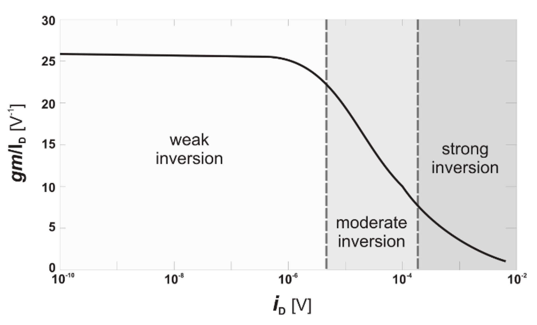
Figure: gm/ID versus iD

Acknowledgement - This research was funded by Universidad Católica de Córdoba (Argentina), the Walloon Region DGO6 BEWARE Fellowships Academia Programme (1410164-POHAR, cofunded by the European Marie Curie Actions), the Belgian FNRS (Fond National pour la Recherche Scientifique) and the Argentinean MINCyT (Ministerio de Ciencia y Tecnología).

May 15, 2020

[paper] Electrical characterization of advanced MOSFETs

Valeriya Kilchytska, Sergej Makovejev, Babak Kazemi Esfeh, Lucas Nyssens, Arka Halder,
Jean-Pierre Raskin and Denis Flandre
Electrical characterization of advanced MOSFETs towards analog and RF applications
IEEE LAEDC, San Jose, Costa Rica, 2020, 
doi: 10.1109/LAEDC49063.2020.9073536

Abstract - This invited paper reviews main approaches in the electrical characterization of advanced MOSFETs towards their target analog and RF applications. Advantages and necessity of those techniques will be demonstrated on different study cases of various advanced MOSFETs, such as FDSOI, FinFET, NW in a wide temperature range, based on our original research over the last years. 

URL: https://ieeexplore.ieee.org/stamp/stamp.jsp?tp=&arnumber=9073536&isnumber=9072949

Acknowledgements - This work was partially funded by Eniac “Places2Be”, Ecsel “Waytogofast”, FNRS - FRFC “Towards Highly-efficient 10 nm MOSFETs”, FP7 “Nanosil” and “Nanofunction” projects. The authors thank our colleagues from CEA-Leti, ST and Imec, and particularly, F. Andrieu, O. Faynot, T. Poiroux, S. Barraud, M. Haond, N. Planes, N. Collaert, C. Claeys, M. Jurczak, B. Parvais, R. Rooyackers, for providing UTBB FD SOI, NW and FinFET devices and valuable discussions.

Jul 25, 2017

[paper] Compact On-Wafer Test Structures for Device RF Characterization

B. Kazemi Esfeh, K. Ben Ali and J. P. Raskin IEEE Fellow
Compact On-Wafer Test Structures for Device RF Characterization
in IEEE TED, vol. 64, no. 8, pp. 3101-3107, Aug. 2017
doi: 10.1109/TED.2017.2717196

Abstract: The main objective of this paper is to validate the radio frequency (RF) characterization procedure based on compact test structures compatible with 50um pitch RF probes. It is shown that by using these new test structures, the layout geometry and hence the on-chip space consumption for complete sets of passive and active devices, e.g., coplanar waveguide transmission lines and RF MOSFETs, is divided by a factor of two. The validity domain of these new compact test structures is demonstrated by comparing their measurement results with classical test structures compatible with 100–150um pitch RF probes. 50um -pitch de-embedding structures have been implemented on 0.18um RF silicon-on-insulator (SOI) technology. Cutoff frequencies and parasitic elements of the RF SOI transistors are extracted and the RF performance of trap-rich SOI substrates is analyzed under small- and large-signal conditions [read more...]


Dec 16, 2015

[video] How to Model RF Passive Components: Capacitors and Resistors

This video explains and demonstrates a method to develop accurate SPICE models from verified S-parameter measurements. By using an easy to follow, step by step procedure, this video walks you through the entire modeling flow for an on-wafer capacitor, using the Keysight Measurement and Modeling Software IC-CAP.

The IC-CAP project can be downloaded, together with a detailed How-to-Use description, and an in-depth tutorial about passive components modeling, applying the demonstrated method.

[VIDEO]